Platform for creating and sharing Circuit Diagram The typical potentiometer will have 3 pins, two power supply pins (+5V and GND), and one pin that connects to an analog input pin on your Arduino to read the value output. To learn how to read data from a potentiometer, and display it in the Serial Monitor, visit the Analog Read Serial example. Hardware Required. Arduino board; Potentiometer

A plain old 555 timer creates voltage spikes, which the digital pot may misinterpret as clock pulses. Figure C shows a test circuit in which I connected the ends of the resistor ladder (pins 3 and 6 of the AD5220) between the power supply and ground. As the Wiper moves between them, its voltage (on pin 5) will vary between 0V and 5VDC.
Digital Potentiometer MCP41100 and Arduino : 4 Steps Circuit Diagram
Digital Potentiometer MCP41100 and Arduino: We know the analog potentiometer , is a three-terminal resistor with a sliding contact that forms an adjustable voltage divider . Potentiometers Many application such like : 1)volume controls on audio equipment. 2) Control the amplifier Gain …
The MCP4231 digital potentiometer circuit that we will build to control the brightness of 2 ultra low-current LEDs, alternating between the 2 so that one is fully bright while the other is off, is shown below. The LEDs must be low-current, because the maximum current that can pass through any of the potentiometer terminals is 2.5mA. Hello, I'm looking for something like the Digital Potentiometer IC X9315 that a 3 wire hall effect sensor can be used as the input. 24v dc motor using china motor controller that has a 100k ohm pot for speed control. I want to replace the 100k pot with a digital pot that I can wire in the hall sensor as the speed controller. Thanks E The difference is a digital potentiometer IC is controlled by software, while a regular potentiometer is controlled manually by a person. Just like a regular potentiometer, a digital Pot IC comes in all different values of resistance. The specific digital potentiometer we will use in this circuit is the MCP4131 IC. The MCP line of

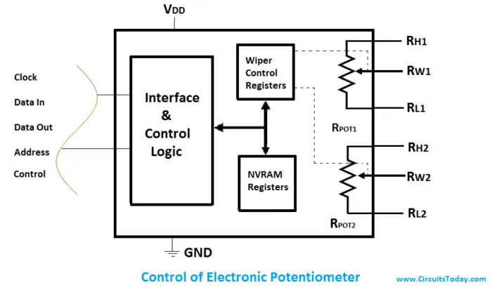
Digital Potentiometer : Circuit, Working, Types and Its Applications Circuit Diagram
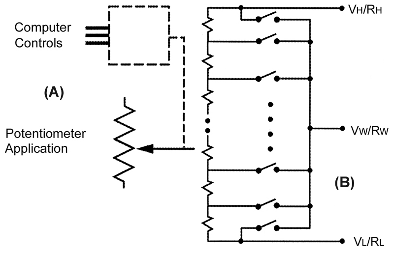
The below picture shows the digital potentiometer circuit diagram in ladder design. The digital resistors are regulated through up/down signals or by protocols like SPI and I 2 C. Digital POT Circuit In Resistor Ladder Design. Digipots are ICs where some of the devices have non-volatile memory and some have no on-boarding memory. The non

How digital potentiometers work, how to use them alone or with Arduino, and practical uses and applications for digital pots. With working project examples a A Digital Potentiometer Circuit Without Arduino!!: Hi there! Potentiometers basically control a certain parameter, such as brightness, contrast, or volume. However those we usually get in the market use knobs. So how do devices control volume, contrast etc with just 2 buttons?? Well, if you've…
