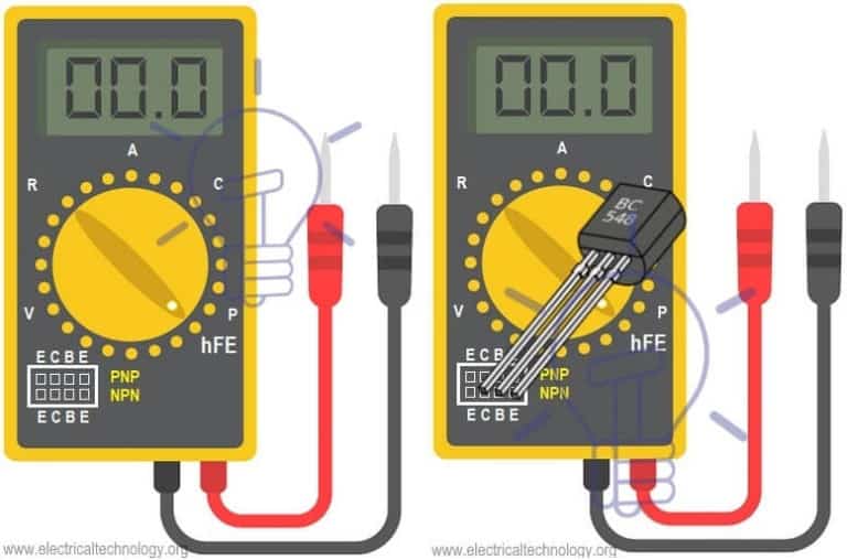
Pin on How to test transistors with ANY multimeter Circuit Diagram To check a transistor in hFE mode, there are 8 pins slot in the multimeter indicated by PNP and NPN as well as E C B (Emitter, Collector and Base). Simply put the three pins of transistor in the multimeter slot one by one in different slots i.e. ECB or CBE (Rotary knob should on hFE mode).

To test your transistor, first clamp the black probe of a multimeter to the transistor's base. Then, touch the red probe to the emitter and read the display to see if the resistance is high or low. Next, move the red probe to the collector, and check that the reading is the same as it was before.
How to Test Transistor with Multimeter Circuit Diagram
In the same manner, we can test a PNP transistor too. Step by Step Testing of NPN Transistor. Set the digital multimeter to Diode or Continuity range. Connect the Positive probe (Red coloured) of multimeter to the base terminal of the transistor. Connect the negative or common probe (Black coloured) of multimeter to the emitter terminal.

Learn how to identify the transistor type, pinout, and measure the voltage drop between its terminals using a multimeter in diode mode. Find out the expected voltages for NPN and PNP transistors and how to interpret the test results.

How to Test a Transistor Using a Digital Multimeter Circuit Diagram
Testing a Transistor with a DMM. A digital multimeter can be used as a fast and simple way to check a transistor for open or shorted junctions. For this test, you can view the transistor as two diodes connected as shown in Below Figure for both npn and pnp transistors.